Pixion’s video output
Hello Pixioneers!
A short post today. Let’s have a quick look at how Pixion will handle video output.
As previously mentioned, I chose to use a VGA interface for its simplicity compared to more modern standards like HDMI or DisplayPort. VGA is well documented and can be implemented relatively easily from scratch on an FPGA.
VGA requires five signals:
- 3 analog color signals:
- red component
- green component
- blue component
- 2 digital synchronization signals:
- horizontal sync (HSYNC)
- vertical sync (VSYNC)
Each color signal is analog, and in our case, we’ve chosen to limit them to 4 levels per channel, that is, 2 bits per color. This means we need to convert digital values to analog voltages, which is the job of a DAC (Digital-to-Analog Converter).
I explored a few DAC topologies (a non-exhaustive list is at the end of this post if you’re curious), and since we only need 2-bit precision, both the R-2R ladder DAC and binary-weighted resistor DAC were good candidates. I ended up choosing the binary-weighted resistor DAC, which is slightly simpler to implement.
This type of DAC uses an op-amp in an adder configuration, where the resistors are selected in powers of two (e.g. R, 2R, 4R).

⚠️ Note: While the binary-weighted DAC is simple for low resolutions like 2 bits, it becomes impractical for higher resolutions due to its sensitivity to resistor tolerances. But for this use case, it’s perfectly fine.
One important detail: VGA cables can be quite long, and at the frequencies used to transmit pixel data, signal reflections can occur if the line isn’t properly terminated. VGA cables are typically matched to 75 Ω impedance, so we need to add a 75 Ω series resistor at the output of each DAC (one per color channel) to match the cable’s impedance.
However, this matching resistor, when paired with the monitor’s internal 75 Ω input impedance, forms a voltage divider, which cuts the voltage in half.
Therefore, to achieve VGA’s required maximum voltage of 0.7 V on the line, our DAC must produce 1.4 V in open circuit for the highest color level.
This voltage drop needs to be considered when scaling the output range of the DAC.
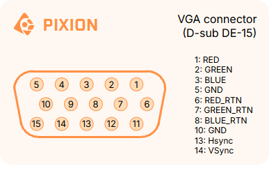
Finally, to physically connect the VGA cable to the PCB, we’ll use a D-sub DE-15 connector, commonly referred to as a VGA connector. Since monitors usually have a female socket and most VGA cables are male-to-male, we’ll place a female connector on the Pixion board as well.
Below is the pinout of the connector, with the relevant pins for our project highlighted:
That’s it for today!
Next time, we’ll explore how Pixion handles audio output, from digital generation to analog conversion and connector choices.
Stay tuned,
Pix’
Some DAC topologies encountered during my exploration:
R-2R ladder DAC, binary-weighted resistor DAC, string DAC, current-steering DAC, segmented DAC, switched-capacitor DAC, PWM DAC, delta-sigma DAC, charge-redistribution DAC.